

Introduction
In this part of the article, we’ll delve into creating the groundwork for our football pitch using Jetpack Compose. We’ll achieve this by strategically drawing various shapes and combining them to form the recognizable football ground.
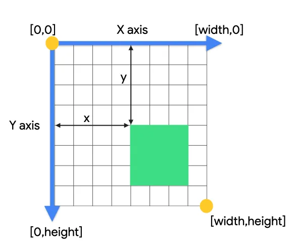
In the context of drawing on a screen using Android’s coordinate system, the concept of X and Y axes doesn’t directly translate to having a specific “base” at the beginning. However, Android’s canvas uses a coordinate system where:
- X-axis (horizontal): This axis represents the width of the screen. The origin (0, 0) is located at the top-left corner of the screen. Positive X values move towards the right, and negative X values move towards the left.
- Y-axis (vertical): This axis represents the height of the screen. The origin (0, 0) is again located at the top-left corner of the screen. Positive Y values move downwards, and negative Y values move upwards.
Create a Canvas
We’ll utilize a Canvas composable to draw our football ground. The modifier argument set to fillMaxSize ensures the canvas covers the entire screen.
| Canvas(modifier = Modifier.fillMaxSize()) { | |
| // ... Drawing code goes here | |
| } |
Drawing the Grass
- Define Green Colors: We’ll establish two green colors to create a textured grass effect. Here, we’re using
Color(0xFF4CBB17)for a vibrant green andColor(0xFF3A9D23)for a slightly darker contrasting shade.
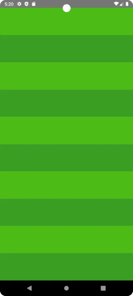
- Calculate Rectangle Height: We’ll divide the canvas height into ten equal parts to draw ten rectangles that will form the base of our grass. Using a loop that iterates from 0 to 9, we’ll draw ten rectangles. The
ifstatement ensures alternating colors (light green and dark green) are used for each rectangle.
| val screenHeight = size.height | |
| val rectHeight = screenHeight / 10 | |
| for (i in 0 until 10) { | |
| val color = if (i % 2 == 0) lightStadiumGreen else darkStadiumGreen | |
| drawRect( | |
| color = color, | |
| topLeft = Offset(0f, i * rectHeight), | |
| size = Size(size.width, rectHeight) | |
| ) | |
| } |
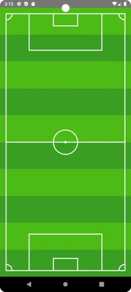
With this approach, we achieve this stunning grass.
Drawing the Field Markings
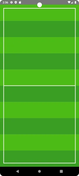
1- Draw the pitch outline
- Define Paths: We’ll use
AndroidPathto define the paths for the center line and the outer boundary of the field. This class is used to define complex shapes or paths by specifying a series of lines, curves, or both. The paths can then be drawn on a canvas.
| val pitchOutline = AndroidPath().apply { | |
| moveTo(50f, 50f) | |
| lineTo(size.width - 50f, 50f) | |
| lineTo(size.width - 50f, size.height - 50f) | |
| lineTo(50f, size.height - 50f) | |
| close() | |
| moveTo(50f, size.height / 2) | |
| lineTo(size.width - 50f, size.height / 2) | |
| } | |
| drawPath(path = pitchOutline, color = Color.White, style = Stroke(3.dp.toPx())) |
- Drawing the Outer Boundary:
moveTo(50f, 50f): This command moves the starting point of the path to coordinates (50, 50). This is typically from the top-left corner, leaving a margin.
lineTo(size.width - 50f, 50f): Draws a line from the current position to the right edge of the canvas, minus a 50px margin.
lineTo(size.width - 50f, size.height - 50f): Draws another line vertically down to the bottom of the canvas, maintaining the margin.
lineTo(50f, size.height - 50f): Draws a line back towards the left edge of the canvas.
close(): Closes the path by drawing a line back to the starting point, completing the rectangle. This outlines the boundary of the field.
- Drawing the Center Line:
After completing the outer boundary, moveTo is used again to reposition at the start of the center line without lifting the “pen”.
moveTo(50f, size.height / 2): Moves to the left margin, halfway down the height of the canvas.
lineTo(size.width - 50f, size.height / 2): Draws a line straight across to the right margin, effectively bisecting the field.
Drawing the Path:
Once the path is defined, drawPath is used to render it onto the canvas.
path = pitchOutline: Specifies the path object to draw, which includes both the outer boundary and the center line.
color = Color.White: Sets the color of the path to white.
style = Stroke(3.dp.toPx()): Sets the style of the path to be a stroke (outline) with a width of 3 density-independent pixels (dp). This makes the lines visible as outlines rather than filled shapes.
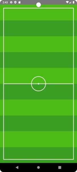
2- Draw the center circles
Now, let’s draw a small filled circle and a big circle outline in the middle of the pitch outline using the drawCirclefunction.
| drawCircle( | |
| color = Color.White, | |
| radius = 10f, | |
| center = Offset(size.width / 2, size.height / 2) | |
| ) | |
| drawCircle( | |
| color = Color.White, | |
| radius = 100f, | |
| center = Offset(size.width / 2, size.height / 2), | |
| style = Stroke(3.dp.toPx()) | |
| ) |
- Small filled circle:
color = Color.White: Sets the color of the circle to white.
radius = 10f: Defines the radius of the circle as 10 float units. The units here are typically pixels, but the exact interpretation can depend on the drawing context and the device’s screen density.
center = Offset(size.width / 2, size.height / 2): Positions the center of the circle at the midpoint of the canvas’s width and height. This effectively places the circle in the center of the screen or drawing area.
This circle is filled with the specified color (Color.White) because no drawing style is specified, which is the default behavior when drawing shapes in Canvas.
- Big circle outline
radius = 100f: Defines a larger radius for this circle, making it 100 float units in size. This significantly increases the circle’s diameter compared to the first one.
center = Offset(size.width / 2, size.height / 2): Positions this larger circle’s center at the same midpoint of the canvas, aligning it with the first circle.
style = Stroke(3.dp.toPx()): Specifies the drawing style as a stroke (outline) rather than a filled shape. The stroke width is set to 3 density-independent pixels (dp), converted to float units with .toPx(), which makes the outline of this circle visible while the inside remains transparent or unfilled.
3- Drawing the Penalty Areas and Corner Arcs
1- Draw Arcs: We’ll employ the drawArc function to create four white arcs at each corner of the field, representing the corner areas. Here, we set useCenter to false as we’re not drawing a full circle around the center point.
- Common Parameters:
color = Color.White: All arcs are drawn in white.
useCenter = false: This indicates that the arc is drawn as just the curve without connecting the ends to the center, effectively creating an open arc rather than a pie slice.
size = Size(100f, 100f): Each arc is drawn within a 100×100 unit square, defining its curvature radius.
style = Stroke(3.dp.toPx()): The arcs are outlined with a stroke width of 3 density-independent pixels, converted to pixel units with .toPx().
- First Arc (Top-Left Corner):
startAngle = 0f: Starts drawing from the 3 o’clock direction.
sweepAngle = 90f: Sweeps a quarter-circle clockwise.
topLeft = Offset(0f, 0f): Positioned at the top-left corner of the canvas.
- Second Arc (Top-Right Corner):
startAngle = 90f: Starts from the 6 o’clock direction.
sweepAngle = 90f: Sweeps a quarter-circle clockwise.
topLeft = Offset(size.width - 100f, 0f): Positioned at the top-right corner, accounting for the arc’s width.
- Third Arc (Bottom-Right Corner):
startAngle = 180f: Starts from the 9 o’clock direction.
sweepAngle = 90f: Sweeps a quarter-circle clockwise.
topLeft = Offset(size.width - 100f, size.height - 100f): Positioned at the bottom-right corner, accounting for both the arc’s width and height.
- Fourth Arc (Bottom-Left Corner):
startAngle = 270f: Starts from the 12 o’clock direction.
sweepAngle = 90f: Sweeps a quarter-circle clockwise.
topLeft = Offset(0f, size.height - 100f): Positioned at the bottom-left corner, accounting for the arc’s height.
2- Draw Penalty Area:
We’ll draw two white rectangles to represent the penalty areas on either side of the field center. The drawRect function with a stroke style will create hollow rectangles.
OUR VIDEO RECOMMENDATION


Jobs
| drawRect( | |
| color = Color.White, | |
| topLeft = Offset(size.width.div(2).minus(100f), 50f), | |
| size = Size(200f, 100f), | |
| style = Stroke(3.dp.toPx()) | |
| ) | |
| drawRect( | |
| color = Color.White, | |
| topLeft = Offset(size.width.div(2).minus(300f), 50f), | |
| size = Size(600f, 300f), | |
| style = Stroke(3.dp.toPx()) | |
| ) | |
| drawRect( | |
| color = Color.White, | |
| topLeft = Offset( | |
| size.width.div(2) - 100f, | |
| size.height - 150f | |
| ), // Adjusted to ensure positive size | |
| size = Size(200f, 100f), | |
| style = Stroke(3.dp.toPx()) | |
| ) | |
| drawRect( | |
| color = Color.White, | |
| topLeft = Offset( | |
| size.width.div(2) - 300f, | |
| size.height - 350f | |
| ), // Adjusted to ensure positive size | |
| size = Size(600f, 300f), | |
| style = Stroke(3.dp.toPx()) | |
| ) |
- Smaller Rectangle :
color = Color.White: The rectangle’s outline color is set to white.
topLeft = Offset(size.width.div(2) - 100f, 50f): Positions the rectangle’s top-left corner by horizontally centering it and moving 100 units to the left, with a vertical offset of 50 units from the top edge of the canvas.
size = Size(200f, 100f): The rectangle’s dimensions are set to 200 units in width and 100 units in height.
style = Stroke(3.dp.toPx()): Outlines the rectangle with a stroke that is 3 density-independent pixels (dp) thick, converted to pixels with .toPx().
- Larger Rectangle :
topLeft = Offset(size.width.div(2) - 300f, 50f): This larger rectangle is positioned similarly but moved 300 units to the left from the center, with the same vertical offset from the top.
size = Size(600f, 300f): This rectangle’s dimensions are set to 600 units in width and 300 units in height, covering a larger area.
Bottom Penalty Area (Mirrored from the Top)
- Smaller Rectangle :
topLeft = Offset(size.width.div(2) - 100f, size.height - 150f): This mirrors the top smaller rectangle’s position at the bottom. The horizontal positioning is the same, but the vertical position is adjusted to place the rectangle 150 units above the bottom edge, accounting for its height and maintaining a 50-unit margin from the bottom, similar to the top.
size = Size(200f, 100f): Keeps the same dimensions as its counterpart at the top.
- Larger Rectangle :
topLeft = Offset(size.width.div(2) - 300f, size.height - 350f): This larger rectangle is positioned to mirror the top goal area. The horizontal positioning is centered and moved 300 units to the left, similar to the top. The vertical position is set to start 350 units above the bottom edge, which considers the rectangle’s height (300 units) and maintains the 50-unit margin from the bottom.
size = Size(600f, 300f): Maintains the same dimensions as the top larger rectangle.
- Draw Small Circles:
We’ll use drawCircle to create two small white circles at the center of each goal line, representing the center of the goalposts.
| drawCircle( | |
| color = Color.White, | |
| radius = 10f, | |
| center = Offset(size.width.div(2), 200f) | |
| ) | |
| drawCircle( | |
| color = Color.White, | |
| radius = 10f, | |
| center = Offset(size.width.div(2), size.height - 200f) | |
| ) |
- Draw the penalty semicircular arc
Common Parameters for Both Arcs
color = Color.White: Sets the color of both arcs to white.
useCenter = false: Indicates that the arc is drawn without a line connecting the ends of the arc to the center, creating an open arc.
size = Size(200f, 100f): Determines the size of the rectangle that bounds the arc. Here, it’s 200 units wide and 100 units tall, affecting the curvature of the arc.
style = Stroke(3.dp.toPx()): Defines the drawing style as a stroke (outline) with a thickness of 3 density-independent pixels, converted to pixels, which outlines the arc without filling it.
First Arc (Top D-Box)
startAngle = 0f: The arc starts from the 3 o’clock position, based on a circle where 0 degrees is at 3 o’clock.
sweepAngle = 180f: The arc extends 180 degrees clockwise, forming a semicircle.
topLeft = Offset(size.width.div(2).minus(100f), 300f): Positions the bounding rectangle’s top-left corner so that the arc is centered horizontally on the pitch. The 300f value places the arc vertically at a specific distance from the top of the canvas, which could represent its position above the top goal area.
Second Arc (Bottom D-Box)
startAngle = 180f: The arc starts from the 9 o’clock position, creating a mirror image of the first arc but positioned at the bottom.
sweepAngle = 180f: Similar to the first arc, it sweeps 180 degrees clockwise, but because of its starting angle, it forms a semicircle opening downwards.
topLeft = Offset(size.width.div(2).minus(100f), size.height.minus(400f)): Positions this arc so that it’s horizontally centered like the first arc but uses the size.height.minus(400f) calculation to place it a specific distance from the bottom of the canvas. This likely positions it above the bottom goal area, mirroring the top arc’s position.
Conclusion
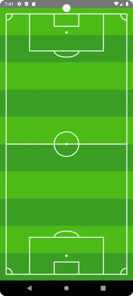
By following these steps and combining the provided code snippets, you’ll have successfully drawn the base structure of a football ground using Jetpack Compose. If you’re interested in adding teams and their player lineups to the canvas, let me know in the comments.
Find the full code here. Thank you
This article is previously published on proandroiddev.com


